
Superabrasive

2026 Top Fuel Pump Carbon Commutator Manufacturers

Fuel-pump reliability depends on small parts doing demanding work. A Fuel Pump Carbon Commutator transfers electrical current while rotating against brushes, often inside a compact, hot, vibration-prone assembly. Its material mix, surface finish, dimensions, and wear behavior can influence motor consistency and service life. Small variations matter.

The market context is changing, but demand needs careful interpretation. OICA’s 2024 production statistics report approximately 92.5 million motor vehicles manufactured worldwide. The International Energy Agency’s Global EV Outlook 2025 reports that electric-car sales exceeded 17 million in 2024, representing more than one-fifth of global car sales. These figures describe broad vehicle trends, not commutator demand directly. Electric vehicles also do not all use conventional fuel-pump assemblies. That distinction is easy to overlook.

This 2026 manufacturer overview should therefore assess more than company size or catalog breadth. Buyers need evidence of stable carbon formulations, controlled machining, brush compatibility, documented inspection, and repeatable supply. Useful questions include whether suppliers can share dimensional tolerances, endurance-test conditions, and batch traceability. A polished brochure is not test data. Public, comparable performance figures for carbon commutators remain limited, so any ranking should state its criteria and acknowledge gaps. The manufacturers worth closer review are those able to connect engineering claims with verifiable production controls and application-specific support. That is a practical standard, though not a perfect one.
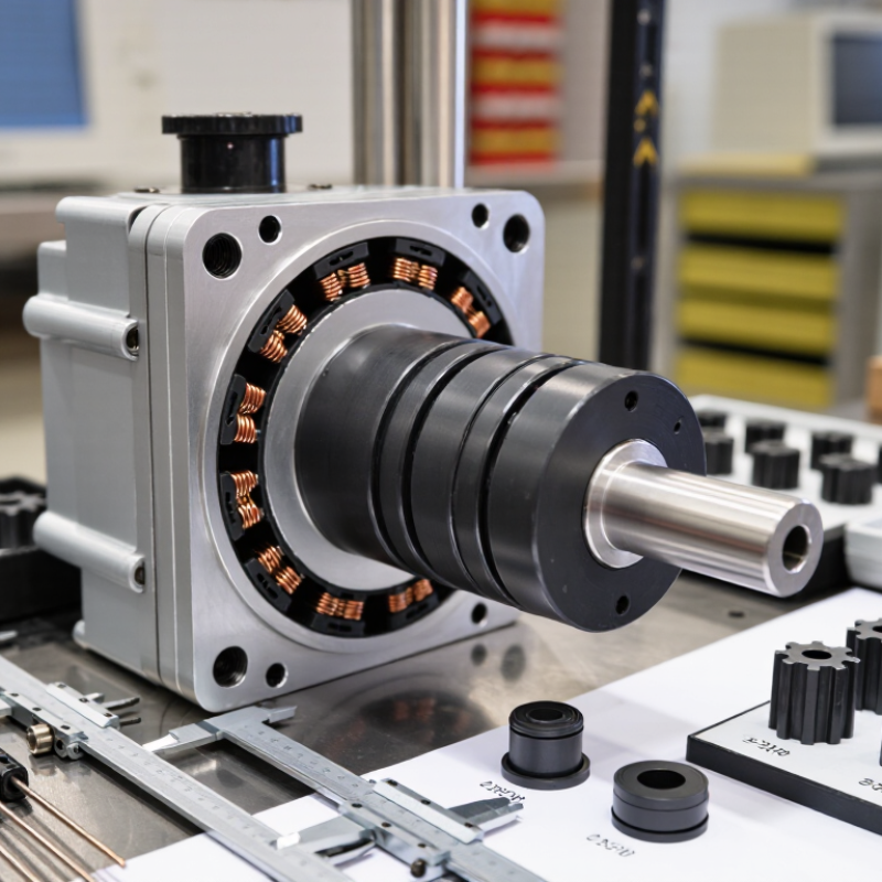
2026 Top Fuel Pump Carbon Commutator Manufacturers

What Is a Carbon Commutator in a Fuel Pump?

What Is a Carbon Commutator in a Fuel Pump?

A fuel-pump carbon commutator is part of the small electric motor that drives the pump. In many product descriptions, “carbon commutator” loosely means the contact system, rather than a commutator made entirely of carbon. The commutator is commonly built from copper segments; carbon brushes press against it and transfer current as the rotor spins. That switching keeps the motor turning. It is small, but its contact surface works continuously in a hot, vibrating environment.

OICA’s 2023 production statistics recorded about 93.5 million motor vehicles built worldwide. This figure describes vehicle production, not fuel-pump demand, but it shows the scale of systems that depend on durable motor components.

In service, brush pressure, surface finish, and electrical load all affect wear. Fine dark dust, uneven contact marks, or rising electrical resistance can signal deterioration. A worn commutator may cause intermittent pump operation, though those symptoms can have other causes. The terminology is imperfect, and inspection alone does not always identify the fault. SAE technical literature on brushed DC motors likewise treats brush-commutator contact as a key factor in motor performance and durability.

How Carbon Commutators Support Fuel Pump Operation

A fuel pump depends on steady motor rotation to move fuel at a consistent rate. In a brushed motor, carbon brushes maintain contact with a rotating commutator, transferring current to the rotor windings. Some designs use carbon-based commutator components. As the rotor turns, the commutator switches the current between windings, helping the motor continue producing torque. That contact matters.

Inside a compact pump, space is tight and operating conditions can be demanding. Brush pressure, commutator alignment, and surface finish affect electrical contact and wear. Excessive resistance can add heat or reduce motor performance; uneven contact may cause faster wear. Small differences matter. A well-made carbon component can support smooth current transfer, but it cannot compensate for poor assembly or unsuitable motor design.

Manufacturers typically assess dimensions, electrical resistance, surface condition, and performance during rotation. Testing under realistic loads is useful because a part that looks sound on a bench may behave differently in a working pump. Carbon also wears over time, so service life depends on material, contact pressure, heat, and operating cycles. There is no perfect material. Even a quiet motor does not tell the whole story; measured performance and consistent inspection provide better evidence.

Materials and Manufacturing Processes for Carbon Commutators

Materials and Manufacturing Processes for Carbon Commutators

A fuel pump carbon commutator must conduct current while resisting friction, heat, and wear. Manufacturers typically blend carbon or graphite with conductive metal powders and carefully selected binders. The exact recipe depends on operating current, contact pressure, and expected service conditions. More metal can improve conductivity, but may also change wear behavior. There is no universal mix. Choosing one requires testing against the pump’s actual duty cycle.

Production begins with powder preparation and controlled mixing. The compound is pressed into segments, then cured or heat-treated to develop strength and stability. Machining brings each segment to precise dimensions, while surface finishing helps create consistent brush contact. Small differences matter. Uneven density or rough edges can cause localized heating and faster wear. Quality checks may include dimensional inspection, electrical resistance measurement, and friction testing. These checks reduce risk, though they cannot perfectly reproduce every field condition.

Tips: Ask for material specifications and test results, not just a “high conductivity” claim. Check segment dimensions and surface finish. Keep in mind that a lower-cost formulation may perform well in one pump but poorly in another. Actual service feedback should guide the final choice.

2026 Top Fuel Pump Carbon Commutator Manufacturers - Materials and Manufacturing Processes for Carbon Commutators

Technical context: In many fuel-pump DC motors, the commutator is made from copper or a copper alloy, while carbon-graphite components serve as brushes that contact it. The material and process information below describes carbon-based electrical contact components; construction varies by motor design.

Material or process area Typical materials Manufacturing process Relevant properties or purpose Common quality checks
Carbon-graphite base Natural or synthetic graphite blended with carbonaceous powders; proportions depend on the electrical and wear requirements. Raw materials are selected, milled, classified, weighed, and blended to achieve a consistent particle-size distribution and composition. Graphite supports electrical conduction and sliding contact. The formulation affects friction, wear, and contact behavior. Incoming-material identification, particle-size analysis, moisture checks, and batch-composition records.
Resin-bonded carbon grade Carbon or graphite powders with a thermosetting resin binder. The blend is formed by pressing or molding and then cured. Cure temperature and time depend on the binder system and part geometry. Resin bonding can provide mechanical strength and is used in some carbon electrical-contact grades; the resulting properties are formulation-specific. Dimensional inspection, visual examination, density measurement, and electrical-resistance testing.
Baked carbon grade Carbonaceous powders with a suitable pitch or other carbon-forming binder. After forming, parts may be baked in a controlled, low-oxygen atmosphere. Carbonization commonly uses temperatures in the approximate range of 800–1,200°C, depending on the material and process. Baking converts the binder to a carbon-rich bond and can improve structural integrity. The exact cycle is grade- and component-dependent. Crack and defect inspection, dimensional checks, bulk-density measurement, and electrical-property testing.
Graphitized carbon grade Suitable carbonized stock made from graphite-forming precursors. Where specified, graphitization is carried out at very high temperature, commonly around 2,500–3,000°C, in a controlled atmosphere. Not every carbon contact grade is graphitized. Graphitization changes the carbon structure and can increase electrical and thermal conductivity; the effect depends on precursor and processing conditions. Electrical resistivity, density, dimensional stability, and microstructure checks against the grade specification.
Impregnated carbon grade Porous carbon or graphite treated with a compatible resin, metal, or other impregnant specified for the application. Impregnation may use vacuum or pressure-assisted methods, followed by a material-appropriate curing or heat-treatment cycle. Impregnation can reduce porosity or modify strength, friction, and wear behavior. The selected treatment must suit the operating environment. Impregnant uptake, mass change, porosity or density, electrical properties, and visual inspection.
Forming and consolidation Prepared carbon mixture appropriate to the selected grade. Depending on the design, the mixture may be die-pressed, molded, or extruded. Consolidation conditions are set to control shape and material uniformity. Consistent forming helps achieve repeatable dimensions and contact geometry; it does not by itself define the final electrical performance. Part dimensions, mass, density uniformity, edge condition, and checks for visible laminations or cracks.
Machining and contact finishing Cured, baked, or otherwise consolidated carbon-based stock. Parts are machined to drawing dimensions. Contact faces may be finished to the specified surface condition and geometry. Accurate dimensions and a suitable contact face support correct fit and stable operation in the intended motor assembly. Dimensional and surface-finish inspection, edge inspection, and verification against the component drawing.
Finished-part validation Completed carbon electrical-contact component, assessed against its application specification. Representative parts may be evaluated in electrical, mechanical, and motor-level tests. Test conditions should reflect the intended operating duty. Performance depends on the complete motor system, including contact pressure, commutator material and finish, current, speed, temperature, and fuel-pump environment. Electrical resistance, wear or endurance testing, dimensional conformity, and application-specific motor validation.

How to Evaluate Fuel Pump Carbon Commutator Manufacturers

How to Evaluate Fuel Pump Carbon Commutator Manufacturers

A carbon commutator may look simple, but small defects can create uneven brush contact, heat, and premature wear. Ask manufacturers for dimensional tolerances, carbon-grade specifications, and test results from production batches—not just a polished sample. OICA reported about 93.5 million motor vehicles produced worldwide in 2023. That scale makes repeatable quality and traceable lots practical supplier checks, not paperwork details. Still, vehicle production figures do not prove commutator performance; component-level evidence matters more.

Request data on electrical resistance, contact stability, wear, and performance under heat and vibration. Check whether tests reflect your pump’s operating current, speed, and fuel environment. Review how the supplier controls raw materials, tooling wear, and rejected parts. A clear process beats a vague promise. Ask for sample inspection records and a corrective-action example, with sensitive customer details removed. One limitation: a short test may not predict years of field use.

Tips: Compare several production lots, not only one sample. Confirm traceability from carbon material to finished part. Visit the production line if feasible; observe dust control, measurement equipment, and how operators handle borderline results. Then document acceptance limits before approval. Small inconsistencies are easy to overlook. Don’t assume low unit price means low total cost.

Leading Fuel Pump Carbon Commutator Manufacturers in 2026

In 2026, leading fuel pump carbon commutator manufacturers stand out through consistent materials, precise machining, and dependable quality checks. A commutator must maintain stable contact with the motor brushes while rotating at high speed. Small defects matter. Uneven segments or rough surfaces can increase wear, noise, and electrical variation. Experienced manufacturers monitor dimensions, surface finish, and material composition across production batches.

Strong suppliers also understand the conditions inside a fuel pump. Heat, vibration, fuel exposure, and repeated starts can challenge carbon components over time. Useful capabilities include controlled molding, accurate slot geometry, and testing under representative operating conditions. Ask how sample parts are inspected and how production changes are documented. A polished catalogue is not enough. Evidence matters more.

Comparing manufacturers requires more than a price check. Review traceability, process consistency, technical support, and the supplier’s ability to meet the required volume. Request clear test criteria and confirm that samples match production parts. One point can be easy to miss: a specification may look complete yet leave wear limits unclear. I would ask for that detail in writing. Careful evaluation helps buyers identify a suitable manufacturing partner without assuming that the largest operation is automatically the best fit.

All search results