
Superabrasive

How to Choose a Weld Ball Valve in 2026?

Choosing a Weld Ball Valve in 2026 starts with the line, not the catalogue image. What fluid will pass through it? What pressure, temperature, and operating frequency must it handle? A valve that looks robust may still be wrong for a hot process line or frequent cycling. Check the body material, seat compatibility, bore, end preparation, and pressure rating against the actual service conditions. Small details matter.

Valve engineer Daniel Mercer puts the principle this way: “Choose the valve for the service it must survive, not the specification that looks impressive.” Treat that as a practical reminder, not a substitute for verified product data. Ask suppliers for material records, dimensional drawings, pressure limits, and welding guidance. Confirm how installation heat may affect seats and seals, and whether the design supports the maintenance plan. A clear answer is useful. A vague answer deserves another question.

This guide explains how to compare welded-end designs, materials, operating features, and supplier documentation. It also covers common trade-offs, such as compact installation versus future service access. For example, a valve tucked behind a pipe rack may be difficult to inspect or replace later. That can be easy to overlook. Specifications alone do not settle every choice; actual site conditions can be messier than the drawing. Use the checklist to narrow options, then confirm suitability with the manufacturer or a qualified engineer before purchase.
How to Choose a Weld Ball Valve in 2026?

What a Weld Ball Valve Is and How It Works

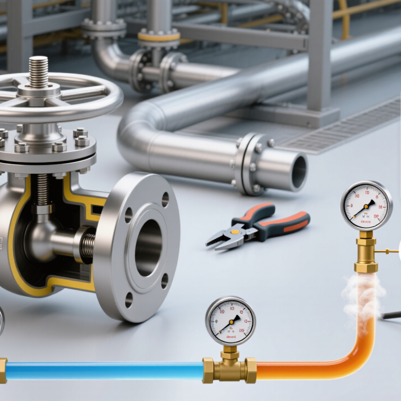
A weld ball valve connects directly to a pipeline through ends prepared for welding. Its compact body contains a drilled ball, a stem, and sealing seats. Turn the stem one quarter-turn, and the ball’s bore lines up with the pipe. The path is open. Turn it again, and the solid side of the ball blocks flow. The handle position gives a quick visual clue, but it does not confirm the valve’s internal condition.

The welded joint creates a permanent connection, so correct sizing and fit-up matter. Check the pipe material, pressure and temperature ratings, bore size, and operating method before selection. During installation, welding heat can damage seats or seals. Follow the valve’s instructions for position, heat control, and any required cooling. A practical inspection also checks alignment and looks for weld spatter near the ball area. One detail is easy to overlook: a valve that turns smoothly before welding may behave differently after the pipe cools.

Tip: Confirm the valve is fully open or closed as specified before welding. Never assume every design uses the same position. After installation, test operation and inspect the joint before putting the line into service.

How to Define Service Conditions and Valve Requirements

A reliable weld ball valve begins with a clear service envelope, not a nominal pipe size. Record the fluid, normal and upset pressures, temperature range, flow direction, and expected operating cycles. Include startup and shutdown conditions. They often differ from steady operation. Note solids, moisture, and corrosive constituents; a small amount of grit can change seat and seal requirements.

Match the body and trim materials to the actual fluid and temperature. ASME B16.34 pressure-temperature rating tables show why pressure class must be checked against both material group and operating temperature. For shutoff expectations, ISO 5208 defines standardized valve pressure tests and leakage criteria; specify the required acceptance level rather than simply asking for “tight shutoff.” For welded ends, confirm pipe dimensions, weld procedure limits, and heat protection for seats and seals. One detail is easy to miss: maintenance access after installation.

Tip: Send suppliers a one-page duty sheet with minimum, normal, and maximum conditions. Add cycle frequency and any solids. Ask them to state assumptions in writing. Some data may be uncertain; mark estimates clearly and verify them before final selection.

How to Select Valve Materials, Size, and Pressure Rating

Choosing a weld ball valve starts with the fluid, temperature, and operating environment. Stainless steel may suit clean water or many mildly corrosive services, while other alloys may be needed for chlorides or aggressive chemicals. Check the body, ball, stem, and seat materials together; one incompatible seal can become the weak point. Small details matter. Confirm material compatibility against actual process conditions, not just the fluid’s name.

Size the valve for required flow, not simply the pipe diameter. A full-bore design can reduce pressure loss and help pass cleaning tools, while a reduced-bore valve may be adequate where space or cost matters. Compare flow requirements, pressure drop, and expected velocity with the valve’s published data. A close match is better than guesswork. Oversizing can make control less stable if the valve is used for throttling, though ball valves are generally selected for on-off service.

Pressure rating must cover the highest expected operating pressure at the relevant temperature, including credible surges. The rating of the complete assembly matters: valve, ends, welds, and connected piping. Check the specified pressure-temperature limits and the project’s design requirements before purchase. I would not assume a higher number on a datasheet solves every issue; temperature can reduce allowable pressure, and installation quality still counts. Verify the weld procedure and inspection plan with qualified personnel.

How to Choose a Weld Ball Valve in 2026? — How to Select Valve Materials, Size, and Pressure Rating

Selection Factor Typical Options or Reference Data How to Select
Valve-end connection Butt-weld (BW) or socket-weld (SW) ends; end preparation and dimensions should match the applicable piping specification. Choose BW for a continuous-bore welded pipeline where the pipe size and wall thickness can be matched. SW is generally used on smaller-bore piping where permitted by the piping code and project specification. Confirm the valve is designed for the intended welding method.
Nominal valve size Common nominal sizes include NPS ½ (DN 15), ¾ (DN 20), 1 (DN 25), 2 (DN 50), 4 (DN 100), and 6 (DN 150). DN values are nominal designations, not exact measured diameters. Start with the required flow rate, fluid properties, allowable pressure drop, and pipe size. Do not select a valve solely by matching the line size; check the valve’s port diameter and flow coefficient (Cv or Kv), especially for reduced-port designs.
Body material Carbon steel, such as ASTM A216 WCB for applicable cast designs; austenitic stainless steel, such as ASTM A351 CF8M for applicable cast designs; or other materials specified for the service. Match the material to the fluid, corrosion environment, operating temperature, pressure, and piping material. CF8M is a cast stainless grade broadly comparable to 316 stainless steel, but it is not immune to corrosion in every chloride or chemical service. Confirm material grade and product form on the datasheet.
Ball and trim material Common choices include stainless steel trim and, where specified, plated or otherwise treated trim. Material availability depends on the valve design. Check corrosion, erosion, solids, and galling risks for the actual fluid. Verify compatibility of the ball, stem, seats, and body as a complete wetted-material set rather than selecting by body material alone.
Seat and seal material Polymeric seats such as PTFE or reinforced PTFE are common; metal seats are available for some higher-temperature, abrasive, or demanding services. Confirm the seat’s allowable temperature and pressure range, chemical compatibility, leakage requirement, and cycle life from the valve manufacturer’s technical data. Temperature limits can vary by compound and design.
Pressure class ASME Class 150, 300, 600, 900, 1500, and 2500 are common class designations. For reference, approximate ambient-temperature ratings for ASTM A216 WCB under ASME B16.34 are about 19.6, 51, 102, 153, 255, and 425 bar, respectively. Select a class whose pressure–temperature rating meets or exceeds the maximum design pressure at the design temperature. These reference values are not universal working-pressure limits: ratings depend on material group, temperature, construction, applicable standard, and the complete valve design.
Design temperature and pressure Use the project’s specified minimum and maximum design temperatures and design pressure, including applicable operating and upset conditions. Check the valve’s pressure–temperature chart and material limits at the actual design temperature. Account for thermal expansion, pressure surges, vacuum conditions, and any required fire-safe or fugitive-emission qualification.
Flow path Full-port valves have a bore closer to the adjoining pipe’s internal diameter; reduced-port valves have a smaller bore and may create a higher pressure drop. Choose full port when low pressure drop, pigging, or passage of solids is required and the design permits it. A reduced-port valve may be suitable where space, weight, or cost is important, provided the flow calculation confirms acceptable performance.
Welding and inspection Relevant requirements may include the project piping code, approved welding procedures, welder qualifications, heat-treatment requirements, and specified nondestructive examination. Confirm end preparation, wall-thickness compatibility, welding sequence, and inspection requirements before purchase. Protect seats, seals, and internal components from welding heat in accordance with the valve manufacturer’s instructions.
Documentation and compliance Typical purchasing documents include the material certificates, pressure-test records, dimensional data, pressure–temperature ratings, and applicable design or testing standards. State the required standards, inspection level, traceability, testing, and certification in the purchase specification. Verify that the selected valve’s design and end connections are suitable for the governing piping code and service.

Selection reminder: Final valve size, material, seat, and pressure class should be confirmed against the project design conditions and the valve manufacturer’s certified datasheet. ASME class numbers are not direct pressure values and must be evaluated using the applicable pressure–temperature rating.

How to Compare Weld-End Designs and Applicable Standards

A weld ball valve should match the pipe, not just the line size. Butt-weld ends suit continuous piping runs and can provide a smooth bore when the valve and pipe are aligned correctly. Check the end preparation, wall thickness, material grade, and pipe schedule before ordering. Small mismatch, big trouble. A slight bore step can disturb flow and complicate inspection.

Socket-weld ends can be practical on smaller-bore piping, but installation needs careful fit-up and access for welding. Confirm the socket dimensions and the required insertion clearance in the project’s piping specification. Trapped crevices may also matter in services where cleanliness or corrosion control is important. This detail is easy to overlook.

Compare standards by what they cover. ASME B16.34 addresses valve design and pressure-temperature ratings; ASME B16.25 covers butt-welding end preparations. Neither alone confirms that a valve suits every piping system. Check the specified piping code, material requirements, inspection rules, and current editions. For pipeline service, API 6D may apply when the project calls for it. Verify the manufacturer’s drawings against the pipe schedule and welding procedure before fabrication. I would still question any selection based only on nominal size.

How to Check Installation, Testing, and Maintenance Needs

Choosing a welded ball valve in 2026 means checking more than pressure class. Confirm pipe schedule, bore, end preparation, materials, and operating temperature against the line specification. Before welding, verify alignment and support; a forced fit can stress the body or distort seats. Keep spatter and grinding dust out of the cavity. Small details matter.

Use a qualified welding procedure and follow the valve maker’s stated heat limits. After cooling, inspect the weld and nearby metal for cracks, undercut, or excessive heat damage. Do not use the valve as a welding ground. Plan shell and seat tests before installation becomes difficult to access. API Standard 598 defines valve inspection and pressure-test requirements. Record the test medium, pressure, duration, and observed leakage. A tidy record helps, but it cannot replace a careful inspection.

Maintenance needs depend on cycling, fluid cleanliness, and how often the line changes temperature. The U.S. Department of Energy’s Operations & Maintenance Best Practices Guide (2010) reports predictive-maintenance savings of 8–12% over preventive maintenance and 30–40% over reactive maintenance. These are program-level benchmarks, not valve-specific guarantees. Track operating torque and check for leakage around the stem and welded ends. Recheck after initial thermal cycles. Inspection intervals deserve review; a schedule copied from another line may not fit this one.

How to Choose a Weld Ball Valve in 2026?

Installation, testing, and maintenance checks to review before selection

How to read this chart: The bars count the practical review topics listed for each project stage; they are not pass rates, test frequencies, or code-mandated totals. Confirm pressure and temperature ratings, materials, welding requirements, and test procedures against the project specification and applicable standards.

  • Installation (5): pressure/temperature rating; material and end-preparation compatibility; alignment and pipe support; qualified welding procedure and personnel; heat control to protect valve components.
  • Testing (4): shell integrity; closure leakage; test medium, pressure, and duration; required examination or testing after welding.
  • Maintenance (4): access and isolation; operating-cycle checks; leakage and corrosion inspection; manufacturer-recommended service and seal replacement.
All search results