
Superabrasive

How to Choose an Automatic Circuit Recloser?

Automatic Circuit Recloser selection affects feeder reliability, equipment protection, and service continuity. It is not simply a matter of choosing the highest voltage rating or the newest control package. The device must match the network’s operating voltage, maximum fault current, load profile, and grounding arrangement. Small mismatches matter. A recloser on a rural overhead line may face long distances, lightning exposure, and widely spaced maintenance visits. An industrial feeder may instead need precise coordination with downstream relays and transformers.

Start with verified system data, not a catalog headline. Check continuous current, interrupting capability, insulation level, operating sequence, and control power. Then review protection settings against upstream and downstream devices, so a local fault does not interrupt a larger section. Communication options deserve attention too. SCADA integration, event records, and remote setting changes can help, but only if staff can support them. Environment matters, from temperature and altitude to corrosion and service access. A neat specification sheet can still hide a poor fit. That is easy to overlook.

This guide explains how to compare recloser types, ratings, controls, and lifecycle needs before purchase. It also highlights where manufacturer documentation and qualified engineering review are essential. No single model suits every feeder. The right choice is supported by verified system studies, a clear maintenance plan, and dependable technical support. Assumptions should be revisited as the network changes. That matters.
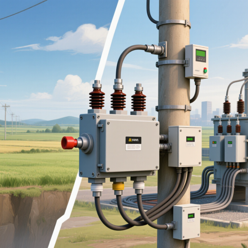
How to Choose an Automatic Circuit Recloser?

Define the Feeder’s Voltage, Frequency, Load, and Maximum Fault Current

Before selecting an automatic circuit recloser, document the feeder’s actual operating conditions. Confirm nominal voltage and highest expected system voltage, then check that the recloser’s rated voltage and insulation level suit the installation. Frequency matters too: a 50 Hz or 60 Hz system requires compatible equipment. Small details matter.

Estimate load using measured demand, not only the feeder’s nameplate rating. Check continuous current during peak periods and allow for planned load growth. Consider motor starting, transformer energization, and cold-load pickup after an outage. These short surges can affect settings and coordination. A spreadsheet helps, but field measurements often reveal uneven loading between phases.

Determine the maximum available fault current at the proposed installation point, using a current utility study or verified network data. The recloser’s interrupting capability must meet or exceed that value, with attention to the rating basis stated by its manufacturer. Also check peak making or withstand ratings where applicable. Recalculate if an upstream transformer, feeder configuration, or source changes. Old fault data can look reassuring—and still be wrong. Record assumptions, including future network changes, so an engineer can review the selection and coordinate protection with nearby devices.

Match Rated Voltage to IEEE C37.60 Classes from 15.5 to 38 kV

Choosing an automatic circuit recloser starts with the system’s voltage class. IEEE C37.60 covers common rated maximum voltages of 15.5, 27, and 38 kV. Do not select a unit by nominal system voltage alone. A 13.8 kV feeder, for example, generally needs equipment rated for the applicable 15.5 kV class. Check the network’s highest operating voltage and the equipment nameplate. Small mismatch, big consequences.

Voltage class also affects insulation coordination. Compare the recloser’s rated maximum voltage and impulse withstand level with the utility’s insulation plan. Then verify the required continuous current and short-circuit interruption ratings. A 27 kV class unit may suit a 24.9 kV system, but only if its fault-duty rating matches the available fault current. Ask the engineer responsible for protection settings to confirm this value.

Installation details matter, too. Consider altitude, temperature, pollution, and whether the recloser is mounted on a pole or in a substation. These conditions can affect insulation performance and maintenance access. In practice, voltage labels are easy to compare; the harder part is confirming that every rating fits the actual feeder. It is tempting to choose extra voltage margin and move on. That can add cost without solving a fault-duty or coordination problem. Verify the standard edition and project specifications before ordering.

Compare Continuous Current and Interrupting Ratings, Including 630 A and 12.5–20 kA

Choose the continuous current rating for the load the recloser must carry during normal operation. A 630 A rating describes continuous current capacity, not the amount of fault current it can interrupt. Check expected peak demand, future load growth, and the equipment’s specified operating conditions. Ambient temperature and enclosure details can affect usable capacity. Check the installation. A rating that looks sufficient on paper may leave little room for growth.

Interrupting ratings, commonly stated in kA, indicate the fault current the device can safely interrupt under specified conditions. Values such as 12.5–20 kA must be compared with the prospective fault current at the installation point and the system voltage. Not a load rating. A 630 A recloser may still need a higher interrupting rating if the available fault current is high. The larger number is not automatically better; protection coordination and the actual fault study matter too. Verify ratings against technical documentation, and ask a qualified protection engineer to review uncertain assumptions. Details get missed. That deserves a second look.

Select Protection Curves and Coordinate Reclosing with Upstream Devices

Choose an automatic circuit recloser by matching its time-current curves to the feeder’s actual fault levels. Plot the recloser, downstream fuses, and upstream relay on the same curve sheet. Check both minimum and maximum fault currents; a setting that coordinates at one point may fail elsewhere. IEEE C37.112 defines inverse-time characteristics used to compare these device curves. Small margins matter.

Reclosing sequences also need coordination. Set the recloser’s shot count and dead time so temporary faults can clear without unnecessarily operating upstream equipment. Check fuse-saving or fuse-blowing behavior against the utility’s protection plan. Include cold-load pickup and transformer inrush, which can resemble faults after an outage. The U.S. Energy Information Administration’s Electric Power Annual reported average customer interruption durations of 5.6 hours in 2022, including major events, and 2.4 hours excluding them. Those figures do not prove a particular recloser setting improves reliability, but they show why restoration and selectivity deserve careful review.

Before approval, test the proposed settings against recorded feeder events and coordination studies. Verify ground-fault sensitivity, fault-current changes, and communication delays where remote controls are involved. Then document the assumptions. One awkward truth: field conditions can outgrow the study. Revisit settings after feeder changes, and do not treat a clean curve plot as proof of perfect coordination.

How to Choose an Automatic Circuit Recloser?

Select a protection curve that clears faults quickly while maintaining coordination with upstream protection.

Illustrative time-current curves use the IEC standard inverse equation. The example assumes a recloser pickup of 200 A and TMS 0.08, an upstream relay pickup of 300 A and TMS 0.40, and a 0.30 s coordination margin. Confirm actual curves, fault levels, reclosing sequence, and dead time against the equipment data and utility protection study; reclosing dead time is not shown on this trip-time chart.

Check Control, Communications, Environmental Ratings, and IEC 62271-111 Compliance

How to Choose an Automatic Circuit Recloser?

Start with the control cabinet, not just the interrupter. Check whether settings are locally adjustable, password-protected, and easy to review after a trip. Confirm the controller records event time, fault current, and reclose sequence. Communications should match the actual network: verify protocol compatibility, signal coverage, and operation during a site power failure. EIA’s 2023 Form EIA-861 reliability tables report utility-level SAIDI and SAIFI data; use local outage patterns to judge which events remote monitoring could help address. Small details matter.

Environmental ratings need to fit the pole or substation, not an ideal test room. Check temperature range, humidity, altitude, pollution exposure, corrosion protection, and enclosure ingress protection. Picture a cabinet facing salt spray, freezing rain, or afternoon sun. A neat specification sheet can still hide a poor field fit. IEC 62271-111:2019 applies to automatic AC circuit reclosers on systems up to 38 kV. Verify the declared voltage, current, and interrupting ratings against the installation, and request evidence of applicable type tests. Compliance is not a substitute for checking coordination with upstream and downstream protection.

Ask how firmware changes are controlled and whether settings can be exported for maintenance records. Review communications-loss behavior, battery backup, and the process for testing trip and lockout functions. These checks take time. But a missed setting or incompatible protocol can complicate fault response. I would also compare the equipment’s stated environmental limits with actual site measurements; assumptions are easy to make, and harder to correct after installation.

How to Choose an Automatic Circuit Recloser? — Check Control, Communications, Environmental Ratings, and IEC 62271-111 Compliance
Selection Dimension What to Check Specification to Confirm Why It Matters
System voltage and frequency Match the recloser’s rated voltage and frequency to the system’s maximum operating conditions. System nominal and maximum voltage; 50 Hz or 60 Hz; applicable insulation level. Voltage and frequency compatibility are fundamental to safe switching and insulation performance.
Continuous current Check normal load current, expected load growth, and any applicable emergency loading conditions. Required rated continuous current, based on the load study and installation conditions. The selected rating must carry the intended load without exceeding the equipment’s thermal limits.
Fault interruption capability Compare the available fault current at the installation point with the recloser’s interrupting capability. Maximum calculated fault current; rated short-circuit breaking current; required making and short-time withstand capabilities. The recloser must safely interrupt and withstand the faults expected on the network.
Insulation and dielectric ratings Confirm power-frequency and impulse withstand levels are suitable for the network and overvoltage environment. Rated insulation levels; system grounding; surge-arrester coordination, where applicable. Insulation coordination helps reduce the risk of flashover and equipment damage.
Operating duty and reclosing sequence Review the required trip-and-reclose sequence, number of shots, dead times, and lockout behavior. Approved protection coordination study; reclosing intervals; single-phase or three-phase operation, as required. The sequence should coordinate with upstream and downstream protection and suit the network’s operating policy.
Control functions Check that the controller supports the required protection, measurement, automation, and event-recording functions. Protection elements and settings; fault indication; metering; event and disturbance records; time synchronization; local and remote operation. Control capabilities determine how well the recloser can protect the feeder and support fault analysis and operations.
Control power and backup Verify the available auxiliary supply and the controller’s behavior during loss of that supply. AC or DC supply requirements; battery backup arrangement; battery monitoring; expected backup duration based on operating requirements. Reliable control power is needed for protection, communication, indication, and remote operation.
Communications and interoperability Confirm the required physical interfaces, network arrangement, protocol support, and cybersecurity provisions. Required protocols may include DNP3, IEC 60870-5-101/104, Modbus, or IEC 61850, subject to verified device support; interface type; network redundancy; access controls. Protocol names alone do not guarantee interoperability. Confirm supported functions, data points, and integration requirements with the control system.
Environmental operating range Check ambient temperature, humidity, solar exposure, altitude, pollution, and any icing or wind conditions at the site. Manufacturer-declared limits for the complete assembly; site altitude; any required derating or special provisions. Environmental conditions can affect insulation, mechanism operation, electronics, and rated performance.
Enclosure and outdoor exposure Assess protection against dust and water ingress, corrosion, ultraviolet exposure, and local contaminants. Declared enclosure IP rating in accordance with IEC 60529, where applicable; corrosion protection; material suitability; maintenance needs. Outdoor durability depends on the actual enclosure design and site exposure, not on a rating alone.
Installation and maintenance Check mounting arrangement, clearances, cable or terminal connections, access for maintenance, and available lifting provisions. Pole, substation, or other approved mounting arrangement; connection details; service and inspection requirements. Correct installation and maintainability support safe access and long-term operational reliability.
IEC 62271-111 compliance Request evidence that the applicable recloser design and ratings conform to the relevant edition and scope of the standard. Declaration of conformity and supporting type-test documentation for IEC 62271-111; verify the applicable national adoption and project requirements. IEC 62271-111 covers automatic circuit reclosers for alternating-current systems up to and including 38 kV. Confirm the exact scope and edition applicable to the project.
Documentation and acceptance Review technical schedules, drawings, test documents, settings files, and commissioning instructions before approval. Completed datasheet; verified rating plate data; test reports; wiring and communication documents; commissioning and maintenance manuals. Document review helps ensure the delivered equipment matches the design, protection study, and operating requirements.

Selection note: Final ratings and settings should be established from the project’s system studies, site conditions, protection-coordination requirements, and applicable standards. Confirm all manufacturer-declared limits and test evidence for the specific configuration being supplied.

All search results