
Superabrasive

How to Choose the Right OLED Module for Your Product?

Choosing the right Oled Module can determine how clearly users read data, trust your interface, and interact with your product. A bright screen may look impressive in a showroom, yet perform poorly under direct sunlight. A high-resolution panel can also increase power consumption, processing demands, and production cost. The best choice depends on the product’s real working conditions.

Engineers should examine screen size, resolution, viewing angle, brightness, contrast, interface type, and operating temperature. A wearable device may need a compact, low-power display with strong outdoor visibility. Industrial equipment may require a larger panel, stable connectors, protective glass, and continuous operation for many hours. Small details matter. A cable that bends repeatedly can become a serious reliability risk.

Supplier experience should also influence the decision. Review technical drawings, sample performance, quality-control records, and replacement policies before approving a design. Ask whether the supplier can maintain consistent brightness, color, and dimensions across production batches. Compatibility testing is essential, especially when the module connects with custom controllers or touch sensors.

Do not choose by price alone.

A practical evaluation includes prototype testing in realistic conditions. Measure readability at different angles, response time with gloves, heat buildup inside the enclosure, and power use during standby. No selection is perfect. Even experienced teams can overlook condensation, software limitations, or future supply changes. That honest uncertainty deserves attention. Careful comparison, documented testing, and clear supplier communication create a more dependable path from concept to market.
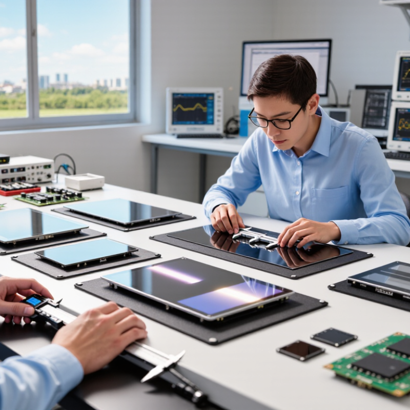
How to Choose the Right OLED Module for Your Product?

Define Your Product’s OLED Display Requirements

Define your product’s OLED display requirements before comparing modules. Start with the user. A wearable may need a compact, curved panel with low power consumption. A laboratory instrument may need sharp text, stable brightness, and reliable operation for long hours.

Record the required active area, resolution, viewing direction, and interface. Measure the enclosure, including cable space and mounting points. Details matter. Consider brightness under direct sunlight and dim performance in dark rooms. Check the operating temperature, storage conditions, expected lifetime, and available supply voltage. If the product includes touch control, confirm glove use, cover-lens thickness, and response speed. A technically suitable panel can still fail when its connector sits two millimeters too close to the housing.

During development, request complete technical documents and test samples. Compare electrical limits, not only the headline resolution. Check startup behavior, image retention risk, color consistency, and power draw with real content. I once underestimated cable flexibility during an early prototype review. The display worked, but assembly became slow and fragile. That mistake changed our checklist.

Prototype under realistic conditions. Test vibration, heat, cold, repeated power cycles, and continuous images. Keep measured results beside the supplier’s specifications. Some requirements may change after testing, and that is normal. Reconsider them carefully rather than forcing a convenient module into the design. A clear requirement sheet helps engineering, purchasing, and quality teams evaluate the same evidence.

Compare OLED Module Types, Sizes, and Resolutions

How to Choose the Right OLED Module for Your Product?

OLED selection starts with module type. PMOLED modules suit compact meters, sensors, and simple interfaces because they use fewer driving components. AMOLED modules support higher resolutions, faster refresh rates, and richer graphics. Rigid OLED usually lowers mechanical risk. Flexible OLED helps curved or space-limited products, but bending radius and lamination quality demand stricter control.

Size and resolution must match viewing distance. A 1.3-inch module may need only 128 × 64 pixels for clear status data. A 6.1-inch interface often benefits from at least 1080 × 2400 pixels. More pixels improve detail, yet they also increase power, memory, and processing requirements. Smaller is not automatically efficient. It can become difficult to read.

Industry data supports careful segmentation. DSCC’s 2024 OLED Shipment Report forecasts smartphone OLED panel shipments above 800 million units in 2024, showing strong demand for high-resolution modules. Omdia’s 2024 Display Long-Term Demand Forecast also identifies OLED strength in premium mobile and television applications. However, market momentum should not dictate every design. In product evaluations, I would compare brightness, contrast, lifetime, connector position, and operating temperature beside resolution. Numbers can mislead. A module with impressive specifications may perform poorly under sunlight or at low temperatures. One overlooked issue is often assembly tolerance. Measure twice.

Evaluate Interface, Power, and Mechanical Compatibility

Choosing an OLED module starts with compatibility, not screen size. Counterpoint Research’s Global Smartphone Display Market Tracker reported that OLED panels exceeded half of smartphone display shipments in 2023. That shift raises expectations for brightness, response, and reliability. Check the interface first. Confirm whether the host supports MIPI DSI, SPI, or another protocol. Match logic voltage, lane count, initialization commands, and refresh timing. A connector may fit physically, yet the firmware can still fail.

Power behavior deserves bench testing. Compare active current, sleep current, startup surge, and brightness settings. OLED pixels emit their own light, so dark images can reduce consumption. High brightness can change that advantage quickly. Measure current at the intended frame rate, not only in standby. The International Energy Agency notes that display efficiency strongly affects electronics energy use, but real products often perform differently from laboratory figures. I have seen prototypes pass a datasheet review and fail after a few hours of thermal testing.

Tips: Request a complete interface table, timing file, and power-sequence diagram. Test the module at minimum and maximum supply limits. For mechanical compatibility, verify active area, bezel clearance, FPC direction, connector height, mounting points, and bend radius. Leave space for tolerances. A one-millimeter mistake can force a new enclosure. Check glass thickness and shock exposure, too. DSCC’s 2024 OLED technology analysis highlights continued expansion beyond phones, where larger modules face stricter thermal and structural demands. This is easy to underestimate. A perfect image is not enough.

How to Choose the Right OLED Module for Your Product?

Evaluation Criteria 0.96-inch Monochrome OLED 1.3-inch Monochrome OLED 2.42-inch Monochrome OLED 2.8-inch Color OLED 3.5-inch Color OLED
Typical Application Compact sensors, wearable devices, status indicators Handheld instruments, compact control panels, meters Portable test equipment, industrial displays, smart controllers Human-machine interfaces, portable instruments, medical devices Advanced control panels, data terminals, visualization interfaces
Display Technology Passive-matrix OLED, monochrome Passive-matrix OLED, monochrome Passive-matrix OLED, monochrome Active-matrix OLED, color Active-matrix OLED, color
Typical Resolution 128 × 64 pixels 128 × 64 pixels 128 × 64 pixels 256 × 64 pixels 320 × 480 pixels
Common Interface I²C or 4-wire SPI I²C or 4-wire SPI 8-bit parallel, 6800/8080 parallel, or SPI 8080/6800 parallel or SPI, depending on controller 8080/6800 parallel, SPI, or RGB interface, depending on controller
Interface Voltage Typically 1.8–3.3 V logic Typically 1.8–3.3 V logic Typically 1.8–3.3 V logic Typically 2.8–3.3 V logic Typically 2.8–3.3 V logic
Supply Voltage Typically 3.0–5.0 V, depending on the module circuit Typically 3.0–5.0 V, depending on the module circuit Typically 3.0–5.0 V, depending on the module circuit Typically 3.0–4.2 V, depending on the controller and module design Typically 3.0–4.2 V, depending on the controller and module design
Typical Active Current Approximately 10–25 mA, depending on brightness and pixel usage Approximately 15–35 mA, depending on brightness and pixel usage Approximately 20–60 mA, depending on brightness and pixel usage Approximately 40–120 mA, depending on image content and brightness Approximately 80–250 mA, depending on image content and brightness
Standby Current Usually below 1 mA with sleep mode enabled Usually below 1 mA with sleep mode enabled Usually below 1 mA with sleep mode enabled Typically below 2 mA with sleep mode enabled Typically below 2 mA with sleep mode enabled
Module Size Range Approximately 27–30 mm × 14–18 mm Approximately 35–40 mm × 25–30 mm Approximately 60–65 mm × 35–40 mm Approximately 75–85 mm × 45–55 mm Approximately 85–100 mm × 55–75 mm
Typical Thickness Approximately 2.0–3.5 mm, excluding mounting hardware Approximately 2.0–3.5 mm, excluding mounting hardware Approximately 2.5–4.0 mm, excluding mounting hardware Approximately 2.5–4.5 mm, excluding mounting hardware Approximately 3.0–5.0 mm, excluding mounting hardware
Mounting Method PCB header, through-hole pins, or flexible cable PCB header, through-hole pins, or flexible cable PCB header, solder tabs, or flexible cable Flexible cable, board-to-board connector, or custom mounting frame Flexible cable, board-to-board connector, or custom mounting frame
Brightness Consideration High contrast; suitable for indoor viewing and shaded enclosures High contrast; suitable for indoor viewing and instrument panels High contrast; suitable for indoor use and controlled lighting High contrast with color graphics; brightness depends strongly on pixel content High contrast with larger graphics; verify brightness for daylight use
Power-Supply Design Impact Moderate power demand; reserve current for peak brightness Higher current demand; check regulator capacity and thermal limits Highest power demand in this comparison; check battery, regulator, and thermal budgets
Firmware and Memory Requirement Low; small monochrome frame buffer or page addressing is often sufficient Low; small monochrome frame buffer or page addressing is often sufficient Low to moderate; interface and graphics buffer requirements depend on the controller Moderate to high; color frame buffers and larger image assets require more memory High; confirm controller speed, RAM, flash storage, and transfer bandwidth
Compatibility Checks Before Purchase Confirm logic voltage, pin spacing, active area, and available enclosure depth Confirm connector orientation, mounting holes, viewing area, and cable clearance Confirm interface mode, controller commands, bezel dimensions, and mounting points Confirm color format, initialization sequence, cable bend radius, and power peaks Confirm interface bandwidth, frame rate, connector pinout, enclosure depth, and heat dissipation
Best Fit When You need a readable, compact, low-power text or icon display You need more viewing area without a major increase in power consumption You need a larger monochrome interface while keeping firmware relatively simple You need color information and graphics in a compact product enclosure You need a large, detailed interface and have sufficient power, memory, and space

Note: Electrical values, dimensions, and current consumption are representative ranges for commonly available OLED module configurations. Always verify the individual module datasheet, connector pinout, initialization sequence, absolute maximum ratings, and mechanical drawing before final product integration.

Assess Brightness, Durability, and Operating Conditions

Choosing the right OLED module starts with its real operating conditions, not its showroom brightness. VESA’s DisplayHDR specifications separate peak brightness from sustained brightness, with certified tiers beginning at 400 cd/m² and extending beyond 1,000 cd/m². A module rated for high peak output may still dim during long video playback. Test it inside the finished enclosure.

Brightness is only one part of reliability. IEC 62341 recommends standardized OLED evaluation for luminance, color, and lifetime, but laboratory results rarely match every field environment. Heat accelerates degradation. Continuous static icons can also create uneven aging. Keep critical graphics moving, reduce unnecessary peak current, and request lifetime data at your expected temperature. Ask for data at 25°C and elevated temperatures. That comparison matters.

Durability depends on moisture control, sealing, vibration, and operating cycles. The Global E-waste Monitor 2024 reports 62 million tonnes of electronic waste generated in 2022, highlighting the cost of short-lived products. Select modules with documented environmental testing, such as thermal cycling and humidity exposure. Confirm the storage limits, too. A rugged specification may hide weak connectors or fragile cover glass. My own design reviews often overvalue brightness and undervalue heat paths. That is a mistake worth revisiting. Use measured data from the complete product, not the module alone.

Verify Suppliers, Prototypes, Costs, and Long-Term Support

Choosing the right OLED module begins with supplier verification, not screen size. Request company registration details, quality certificates, production records, and traceable material information. A capable supplier should explain brightness, viewing angle, temperature limits, lifetime, and batch variation clearly. Ask for recent inspection reports. Vague answers are warning signs.

Never approve a module from drawings alone. Order prototypes and test them inside the real enclosure. Check connector alignment, startup time, touch response, readability under direct sunlight, and performance after repeated power cycles. Run samples at low and high temperatures when the product requires it. One prototype can look perfect. It may still hide uneven brightness or unstable communication. I have seen teams skip vibration testing because the device seemed stationary; field installation later proved that assumption wrong.

Calculate more than the unit price. Include tooling, custom firmware, inspection, packaging, shipping, replacement stock, and engineering changes. Ask whether the quoted price depends on a minimum order. Also confirm lead times during shortages, not only during normal production. Long-term support matters. Obtain written commitments for documentation updates, compatible replacements, repair guidance, and notice before component changes. A supplier may promise support enthusiastically, yet provide little evidence. Request a named technical contact and a realistic escalation process. Keep every approval sample and test result. Memory is not a quality system.

How to Choose the Right OLED Module for Your Product

Recommended evaluation weighting for supplier verification, prototyping, cost control, and long-term support

Use this 100-point evaluation framework when comparing OLED modules. Supplier verification and prototype evidence should receive the greatest weight because manufacturing capability, sample performance, yield, and reliability directly affect production risk. Cost should be evaluated as total cost of ownership, including tooling, engineering changes, testing, logistics, and replacement risk.

Article Source:

All search results