
Choosing an Industrial Power Supply is not just a matter of matching the output voltage on a label. A unit rated for 24 V may still fail to support a system’s actual load, startup surge, or operating environment. Check the required voltage and current, then allow sensible headroom for continuous operation. A small control cabinet on a factory floor faces different demands from a clean, temperature-controlled test bench.
Look closely at the details. Motors, relays, and other inductive loads can draw brief startup currents that ordinary steady-state calculations miss. Heat matters, too: a supply rated at full output in cool conditions may need derating inside a warm, crowded enclosure. Consider efficiency, ripple, mounting space, cooling, and protection against overloads or short circuits. Verify that the specifications and approvals suit the equipment and installation where the unit will be used.
Measure twice.
A neat spreadsheet can still miss a real-world detail, such as a long cable run or a cabinet fan that has stopped working. That is worth admitting before choosing a model. Compare manufacturer datasheets, check the load profile, and confirm performance under expected temperature and input-voltage conditions. If a specification is unclear, ask the manufacturer rather than relying on a product title or sales summary. The right choice balances electrical performance, physical fit, reliability, and service needs. This guide explains how to assess those factors and select a supply that fits the application—not merely one that looks adequate on paper.
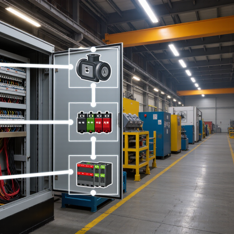
Identify every load before choosing an industrial power supply. Record each device’s voltage, steady-state current, and startup demand. Note which loads switch on together. A PLC drawing 0.4 A is different from a relay bank that briefly pulls several times its normal current. Include temperature, enclosure ventilation, and expected operating hours; heat can reduce a supply’s usable output. Nameplate totals alone can mislead.
The U.S. Department of Energy’s Improving Motor and Drive System Performance sourcebook reports that motor-driven systems account for about 69% of electricity use in U.S. manufacturing. That figure is a reminder to separate motor loads from sensitive control loads. A motor’s startup surge may disturb a shared control rail, even when average demand looks acceptable. Check the equipment manuals for peak-current duration, then compare the combined demand against the supply’s derating curve. Add headroom where measurements or future expansion justify it, rather than applying an arbitrary margin. A spreadsheet can still miss a short surge.
Tips: Measure voltage at the load during startup, not only at the supply terminals. Record the worst case. Recheck the estimate after commissioning.
| Load or application | Typical load requirements | Key operating considerations | Selection guidance |
|---|---|---|---|
| PLC and control circuitry | 24 V DC; example load: 1.5 A (36 W) | Requires a stable DC output; account for connected I/O modules and any expansion. | Allow capacity for the full measured load plus a practical reserve, commonly around 20–25% when conditions permit. |
| Industrial sensors | Often 24 V DC; example group load: 0.8 A (19.2 W) | Add the current draw of every sensor, transmitter, and interface device; check the specified voltage range. | Confirm the supply maintains adequate voltage at the load, including voltage drop in long cable runs. |
| Relay and contactor coils | Commonly 24 V DC; current varies by coil and operating state | Several coils may energize simultaneously; inductive loads can generate voltage transients when switched. | Size for the maximum simultaneous pickup current and use suitable suppression where required by the load or control design. |
| Solenoid valve | Example: 24 V DC, 0.5 A while energized (12 W) | Check whether the coil is continuous-duty or intermittent-duty and whether multiple valves can switch together. | Use the coil’s specified current and duty rating; include simultaneous operation and switching effects in the calculation. |
| DC motor or actuator | Varies by motor; running current may be substantially lower than startup or stall current. | Starting, acceleration, reversal, and stall conditions can cause brief high-current demand. | Check motor and drive specifications for peak current and duration; verify the supply’s overload behavior and transient response. |
| Industrial communication equipment | Often 24 V DC; example device load: 0.4 A (9.6 W) | Include all switches, gateways, and accessories; consider the effect of a power interruption on communications. | Check total continuous demand and, where continuity is essential, assess a suitable backup or redundancy arrangement. |
| Control cabinet operating conditions | Input supply, ambient temperature, installation method, and required output voltage depend on the site. | High temperature, restricted airflow, altitude, dust, vibration, and cabinet layout can affect permitted operation. | Check the supply’s derating curves, input-voltage range, mounting clearances, and applicable environmental ratings for the actual installation. |
Example load values are illustrative, not equipment specifications. Confirm each device’s rated voltage, continuous current, peak or inrush demand, duty cycle, and environmental limits before sizing the power supply.
Start with the equipment’s required output voltage, then list every device the supply will feed. Add their normal operating currents to estimate the total load. For example, three devices drawing 0.6 amps each need at least 1.8 amps at that voltage. Multiply voltage by current to find power: 24 volts × 1.8 amps equals 43.2 watts. Check each device’s label or manual; guessing from appearance is unreliable.
Allow room for startup surges and future additions. Motors, relays, and some electronic loads may briefly draw more current than they use continuously. A practical margin of 20–30% can help, but the right allowance depends on the load and operating conditions. Also check whether the supply’s rated output falls at high temperatures or inside a warm, enclosed panel. Small details matter.
Tips: Write down voltage, continuous current, and peak current for each load. Add the currents, then calculate watts. Don’t treat a larger supply as an automatic fix; confirm voltage compatibility and any minimum-load requirements. If measurements disagree with the nameplate, investigate before choosing. A little uncertainty is normal, but document your assumptions.
An industrial power supply must suit the conditions inside its enclosure, not just the room. Check the expected temperature range, humidity, dust, and vibration. A cabinet beside a furnace may run far hotter than the factory floor. Condensation can also form after a cold shutdown. Dust matters. Oil mist and metal particles may require a sealed enclosure or added protection. Compare the supply’s published ratings with the actual installation conditions, including altitude where relevant.
Tips: Measure the cabinet temperature during a normal production shift. Leave the specified clearance around vents, and keep cables away from hot surfaces. Check the unit’s ingress-protection rating against likely exposure; a rating alone does not guarantee suitability for every contaminant.
Review electrical safety before installation. Confirm the input voltage, grounding method, and required protective devices match the equipment design. Check overload and short-circuit behavior, and make sure applicable safety certifications cover the intended region and use. Vibration can loosen terminals over time, so inspect mounting and connection requirements. One detail is easy to miss: a supply may meet its temperature rating while enclosed, yet still need derating at higher temperatures. Verify this in its technical documentation. When conditions are uncertain, record measurements and ask a qualified engineer to review them before selecting a unit.
Industrial power supplies differ in noise, size, efficiency, and fault tolerance. Linear units provide low electrical noise, but they are usually heavier and less efficient. Switching supplies are compact and efficient, though their electromagnetic interference needs careful control. DIN-rail models suit control cabinets; enclosed units protect against dust and accidental contact. Match the format to the installation, not just the price.
Check output voltage and current against the load’s startup surge, not only its steady draw. Allow for temperature derating, vibration, input-voltage variation, and enough headroom for future sensors. Ripple, isolation, overload protection, and hold-up time also matter. A quiet supply can still be the wrong one. I still double-check startup current; it is easy to overlook. For critical lines, redundant supplies can keep a controller running after one unit fails.
Uptime Institute’s 2024 Annual Outage Analysis found that 54% of respondents’ most recent significant outages cost over $100,000. That is data-center evidence, not a factory-specific forecast, but it shows why continuity deserves attention.
The U.S. Department of Energy’s 2022 Industrial Decarbonization Roadmap estimates industry uses about 30% of U.S. primary energy. Even small efficiency differences can matter across many continuously operating cabinets. Check datasheets under your actual load and ambient temperature; headline efficiency alone can mislead.
A suitable industrial power supply must fit the job and the conditions around it. Check that its certifications apply to the exact model, input range, and intended installation environment. A certificate for a product family may not cover every configuration. Ask for current documentation, and compare the marked ratings with the equipment specification. Small details matter.
Installation needs can change the choice. Confirm the available panel space, mounting orientation, wiring access, and ambient temperature. A supply that looks adequate on a bench may need derating inside a warm, crowded cabinet. Leave room for airflow and for a technician’s tools. Plan for access. Check the manual for terminal torque and protective-device requirements, rather than relying on assumptions. I would still verify these details against the actual enclosure; drawings often miss a cable bend or nearby heat source.
Maintenance is easier when indicators are visible and the unit can be replaced without dismantling adjacent equipment. Consider dust, vibration, and expected operating hours. Set a practical inspection interval based on site conditions, and record temperature readings or unusual alarms. Look for loose connections, blocked vents, and discoloration during scheduled checks. Some wear is hard to spot, so a clean exterior is not proof of healthy operation. Keep the service instructions available near the equipment, where they are useful.
| Cookie | Duration | Description |
|---|---|---|
| cookielawinfo-checkbox-analytics | 11 months | This cookie is set by GDPR Cookie Consent plugin. The cookie is used to store the user consent for the cookies in the category "Analytics". |
| cookielawinfo-checkbox-functional | 11 months | The cookie is set by GDPR cookie consent to record the user consent for the cookies in the category "Functional". |
| cookielawinfo-checkbox-necessary | 11 months | This cookie is set by GDPR Cookie Consent plugin. The cookies is used to store the user consent for the cookies in the category "Necessary". |
| cookielawinfo-checkbox-others | 11 months | This cookie is set by GDPR Cookie Consent plugin. The cookie is used to store the user consent for the cookies in the category "Other. |
| cookielawinfo-checkbox-performance | 11 months | This cookie is set by GDPR Cookie Consent plugin. The cookie is used to store the user consent for the cookies in the category "Performance". |
| viewed_cookie_policy | 11 months | The cookie is set by the GDPR Cookie Consent plugin and is used to store whether or not user has consented to the use of cookies. It does not store any personal data. |