
Buying the right Relief Valve Block is a small component decision with plant-wide consequences. In hydraulic, chemical, and process systems, the block must isolate, test, and support safe relief-valve maintenance. Grand View Research estimated the global industrial valves market at USD 78.1 billion in 2023. Its report also projects a 4.4% compound annual growth rate through 2030. More equipment means more supplier choices. It also means more specification risk. The cheapest block may match the drawing. It may not match the operating reality.
This guide presents seven practical buying checks for pressure rating, material compatibility, port configuration, flow path, temperature range, certification, and service access. API 520 Part I provides recognized guidance for pressure-relief device sizing and selection. API 576 addresses inspection practices for pressure-relief devices. These references do not replace engineering review. They create a dependable starting point. The U.S. Chemical Safety Board’s investigation reports also show how poor maintenance, weak procedures, and incomplete process knowledge can contribute to serious process-safety events. A correctly selected block cannot repair a weak safety culture.
Look closely at the details. A stainless-steel body can still fail when seals, threads, or tubing are mismatched. A compact manifold can still create awkward access beside a hot pipe. Ask for material certificates, pressure-test records, temperature limits, and traceable documentation. Confirm whether the design supports lockout, venting, and testing under your site procedures. Do not rely on catalogue photographs alone. They hide critical dimensions. No checklist is perfect. Real installations often expose assumptions that looked reasonable during procurement. The best decision combines standards, supplier evidence, operator experience, and an honest review of what could go wrong.
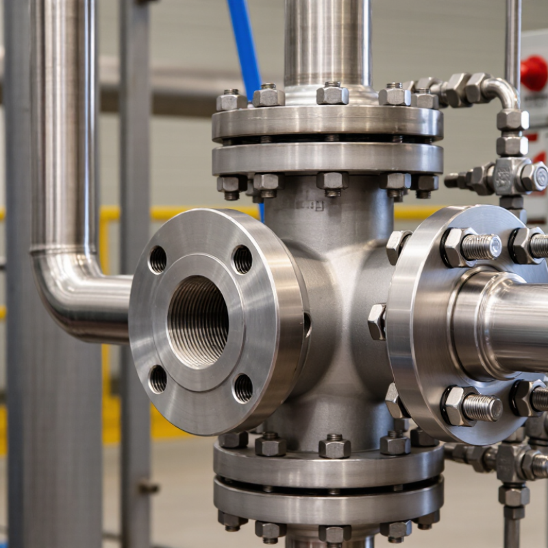
A relief valve block should begin with service definition, not catalog selection. Under ASME Section VIII, identify the vessel’s design pressure, temperature, set pressure, accumulation limit, and relieving scenario. API 520 Part I then guides capacity sizing, inlet pressure-loss checks, and discharge reaction-force evaluation. OSHA Process Safety Management covers processes containing 10,000 pounds or more of flammable liquids or gases, making documented relief protection especially important.
Record fluid phase, molecular weight, viscosity, corrosion tendency, and required flow. Include fire exposure, blocked outlet, thermal expansion, and control-valve failure cases. A practical detail matters: write the expected relieving temperature beside the pressure value. Engineers often miss this connection. I have seen otherwise careful specifications use normal operating temperature instead.
A relief valve block may support maintenance, but it must not create accidental isolation. Review the arrangement against the applicable ASME VIII rules, API 520 guidance, and site procedures. Check locking provisions, bleed routing, valve position indication, and access for inspection. The American Petroleum Institute’s Process Safety Site Assessment program repeatedly emphasizes mechanical integrity and operating discipline as key risk controls. That evidence supports a conservative review, though it does not replace a formal hazard study.
Confirm inlet losses, outlet backpressure, reaction loads, drainage, and discharge location. API 520 and API 521 should be read together where disposal and flare systems interact. Do not approve a block from pressure data alone. Field conditions can disagree with drawings. Recheck them.
7 Tips for Buying the Right Relief Valve Block
Set pressure is not the same as operating pressure. Set it above normal pressure, but below the equipment’s allowable working limit. In many pressure systems, standard accumulation is limited to 10% above the valve’s set pressure. That margin supports controlled relief without overstressing the vessel. Buying tip: confirm the design pressure, operating range, fluid type, and required capacity before selecting a valve block. A small mismatch can create repeated lifting, leakage, or unstable performance.
Fire exposure changes the calculation. Under applicable pressure-relief standards, allowable accumulation may reach 21% during a documented fire scenario. This does not mean every installation should use 21%. The fire case must be evaluated with heat input, wetted surface area, fluid properties, and relief capacity. Tip: ask a qualified engineer to verify whether the 21% limit applies to your equipment and jurisdiction. Guessing here is risky.
Choose materials that tolerate the process temperature and chemical environment. Check inlet losses, discharge routing, isolation arrangements, and inspection access. A compact block may look convenient, yet poor flow geometry can reduce real capacity. I have seen specifications focus heavily on set pressure while ignoring maintenance clearance. That is an easy mistake to repeat. Verify certification, test records, and adjustment controls before purchase. Also review the supplier’s sizing assumptions. Clear documentation builds confidence, but field conditions still deserve a second look.
| Tip | Buying Dimension | What to Check | Typical Requirement or Data | Why It Matters |
|---|---|---|---|---|
| 1 | Confirm the Set Pressure | Compare the valve set pressure with the protected equipment's MAWP. | Set pressure should normally be at or below the equipment MAWP. Example: MAWP 10.0 barg; set pressure should not exceed 10.0 barg unless the applicable code permits otherwise. | Prevents the relief device from allowing pressure to rise above the vessel's permitted design limit during normal protection. |
| 2 | Apply the Correct Accumulation Limit | Identify whether the scenario is ordinary overpressure, multiple-device operation, or external fire exposure. | 10%: common standard case 21%: fire exposure case Use the governing design code and process hazard analysis to confirm the allowable value. | The accumulation limit determines the maximum permitted pressure while the relief device is flowing. |
| 3 | Size the Flow Capacity Correctly | Specify the required relieving rate, fluid phase, temperature, molecular weight, and compressibility where applicable. | For liquids, provide required flow in m3/h or L/min. For gases or vapors, provide mass flow in kg/h or lb/h and relieving conditions. | A valve can have the correct pressure setting but still be undersized for the credible overpressure scenario. |
| 4 | Select Compatible Materials | Match body, trim, seals, and spring materials with the process fluid, temperature, and corrosion conditions. | Common material choices include carbon steel for compatible services, stainless steel for improved corrosion resistance, and elastomer seals selected for the actual fluid and temperature. | Material incompatibility can cause leakage, corrosion, swelling, embrittlement, or loss of pressure-control performance. |
| 5 | Check the Connection and Installation | Verify inlet and outlet size, pressure class, connection type, flow direction, and discharge routing. | Typical connection options include threaded, flanged, socket-weld, or butt-weld ends. Inlet piping pressure loss should be kept within the applicable installation guidance. | Incorrect connections or excessive inlet pressure loss may cause instability, chattering, reduced capacity, or difficult maintenance. |
| 6 | Choose the Appropriate Valve Type | Determine whether a spring-loaded, pilot-operated, pressure-only, or pressure-and-vacuum design is suitable. | Spring-loaded valves are widely used for general pressure protection. Pilot-operated designs may be considered for high flow, high backpressure, or tighter operating margins. | The valve design influences response stability, allowable backpressure, maintenance requirements, and suitability for the process. |
| 7 | Verify Certification and Maintenance Support | Request sizing calculations, test certificates, material documentation, inspection records, and service instructions. | Documentation should identify set pressure, capacity, relieving medium, temperature, materials, connection details, and applicable code or standard. | Complete records support commissioning, periodic testing, regulatory compliance, troubleshooting, and future replacement. |
| Reference note: The 10% and 21% accumulation values are commonly associated with standard overpressure and fire-exposure relief scenarios under widely used pressure-vessel design practices. Always confirm the final limits, sizing method, and installation requirements against the applicable jurisdictional code, equipment design code, and process hazard assessment. | ||||
Choosing the right relief valve block starts with the required relief rate, not the pipe size.
API 520 Part I provides sizing methods for gas, steam, and liquid service. Gather set pressure, relieving temperature, molecular weight, compressibility, viscosity, and allowable backpressure. Small errors here can produce a seriously undersized outlet.
Define every credible scenario under API 521, including blocked discharge, utility failure, tube rupture, thermal expansion, and external fire. Fire exposure is not a simple percentage of normal flow.
API 521 considers wetted surface area, environmental conditions, insulation, and fluid vaporization data. Calculate each case separately, then select the governing load.
Do not average scenarios. That shortcut is tempting.
Check certified flow capacity against the calculated rate, using the applicable API 520 coefficient and correction factors. Review inlet pressure loss, outlet backpressure, reaction forces, and drainability. A compact block can still restrict maintenance access or trap liquid.
In field reviews, I have seen clean calculations fail because backpressure was copied from an old datasheet. It happens. Recheck it.
Industry process-safety investigation reports repeatedly show that weak assumptions and incomplete design records contribute to overpressure events. Keep the source data visible.
Record fluid properties, scenario assumptions, calculation revisions, and the reason for choosing the final block size. A second review is worthwhile.
The valve is only as reliable as its least-supported input.
Choosing the right relief valve block starts with service conditions, not catalog photos. In field reviews, I record fluid, design pressure, temperature, and exposure time. Then I compare the block’s material and rating with ASME B16.34 requirements. This standard addresses valve construction, pressure-temperature ratings, materials, and testing expectations. A stainless steel block may look suitable, yet its rating can fall sharply at elevated temperatures. Check the table, not the color.
For sour service, NACE MR0175/ISO 15156 becomes critical. It addresses material resistance to sulfide stress cracking and related damage in hydrogen sulfide environments. Confirm the exact alloy, hardness limits, heat treatment, and environmental restrictions. Do not accept “NACE compliant” as sufficient evidence. Request traceable material certificates and review the applicable edition with a qualified engineer. Small omissions matter here.
I also verify connection size, pressure class, seals, thread form, and compatibility with the relief device. The block must not create an unintended restriction or isolation risk. Ask whether its rating remains valid during cold starts, cleaning, or pressure surges. These details are easy to miss. One practical mistake is treating ASME B16.34 and NACE MR0175 as interchangeable; they are not. One governs valve design and ratings, while the other guides material suitability for defined sour environments. Document assumptions, because operating data is often incomplete and early selections may need revision.
Buying the right relief valve block requires more than matching size and pressure rating. In practical inspections, API 527 leakage results often reveal problems that visual checks miss. Confirm the test medium, test pressure, hold time, and measured leakage rate. The report should identify the exact valve, not just a product family.
Ask for hydrotest records covering the pressure boundary. These tests support structural confidence, while API 527 testing evaluates seat tightness. They are different checks. Do not accept one as a substitute for the other. Review the test date, calibrated gauge numbers, acceptance criteria, and inspector’s approval. Small details matter.
Traceability should continue from raw material to final shipment. Look for heat numbers, material certificates, machining records, calibration certificates, and serial-number links. Documentation should follow a controlled quality process aligned with applicable ISO requirements. A neat certificate is not enough. Verify that names, dates, pressures, and identification numbers agree across every document. One mismatch can delay commissioning.
Field experience also suggests checking revision control. Old forms sometimes remain in circulation. That is an easy mistake. Request clarification when a report lacks units or defines leakage vaguely. Suppliers should explain deviations in writing, with technical evidence. I have seen complete-looking files fail a basic cross-check. That is uncomfortable, but useful: reliable purchasing depends on questioning paperwork before the valve reaches a critical system.
| Cookie | Duration | Description |
|---|---|---|
| cookielawinfo-checkbox-analytics | 11 months | This cookie is set by GDPR Cookie Consent plugin. The cookie is used to store the user consent for the cookies in the category "Analytics". |
| cookielawinfo-checkbox-functional | 11 months | The cookie is set by GDPR cookie consent to record the user consent for the cookies in the category "Functional". |
| cookielawinfo-checkbox-necessary | 11 months | This cookie is set by GDPR Cookie Consent plugin. The cookies is used to store the user consent for the cookies in the category "Necessary". |
| cookielawinfo-checkbox-others | 11 months | This cookie is set by GDPR Cookie Consent plugin. The cookie is used to store the user consent for the cookies in the category "Other. |
| cookielawinfo-checkbox-performance | 11 months | This cookie is set by GDPR Cookie Consent plugin. The cookie is used to store the user consent for the cookies in the category "Performance". |
| viewed_cookie_policy | 11 months | The cookie is set by the GDPR Cookie Consent plugin and is used to store whether or not user has consented to the use of cookies. It does not store any personal data. |