What Are the Top Types of Grinding Machines in 2026?
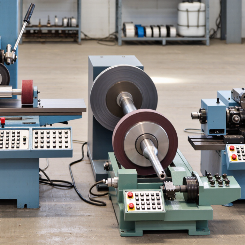
Grinding machines are often mistaken for finishing tools. In practice, they shape dimensions, surface texture, and fit through controlled abrasive cutting. The choice matters. A surface grinder works across a flat face; a cylindrical grinder follows a rotating workpiece. Centerless machines support parts between a grinding wheel and a regulating wheel, without centers. Tool-and-cutter grinders sharpen complex edges, while internal grinders reach bores that other machines cannot access easily. Each leaves a different mark on the shop floor: a flat reference plane, a precise shaft, or a clean internal diameter.
The market is also changing. Grand View Research estimated the global grinding machines market at about US$5.0 billion in 2023 and projected continued growth through 2030. Such forecasts are estimates, not guarantees; demand varies with manufacturing investment and regional conditions. Stephen Malkin, co-author of Grinding Technology: Theory and Applications of Machining with Abrasives, emphasizes a useful principle: grinding performance depends on the interaction between abrasive grains, the wheel bond, and the workpiece. That interaction is easy to overlook. It also explains why machine type alone does not determine accuracy: wheel choice, dressing, coolant, and setup matter. This guide compares the main types of grinding machines in 2026, including where each excels, what it struggles with, and which details buyers should verify before choosing. A small caveat: production needs differ, so no single machine is “best” for every shop.
Classify Grinding Machines by Process and ISO 16089:2015 Safety Scope
What Are the Top Types of Grinding Machines in 2026?
Grinding machines are often classified by the work they perform: surface, cylindrical, centerless, tool-and-cutter, or bench grinding. These process labels describe the operation, not the machine’s safety category. A surface grinder moves a workpiece beneath a rotating wheel; a centerless grinder supports parts between a wheel and a regulating wheel. The details matter.
ISO 16089:2015 adds a separate safety-based classification for stationary grinding machines. It groups machines by control and automation: Group 1 covers manually controlled machines without mechanically controlled axes; Group 2 includes machines with mechanically controlled axes and limited numerical control; Group 3 covers numerically controlled machines. The standard’s scope helps users identify relevant safeguards, but a group label does not replace a machine-specific risk assessment. That distinction matters.
The U.S. Bureau of Labor Statistics reported 5,283 fatal work injuries across all industries in 2023; this figure is not specific to grinding. It is broad context, not proof of grinder-related risk. In practice, assess wheel guarding, workholding, access points, and control behavior for the actual machine and task. A worn wheel or a poorly secured part changes the picture quickly. ISO classification is useful, but it can’t capture every shop-floor condition.
Compare Surface Grinders by Table Travel and 2-Axis or 3-Axis Control
In 2026, compare surface grinders by usable table travel, not just overall machine size.
A 600 mm longitudinal stroke may suit compact dies, while longer travel can help with rails or wide plates. Check cross travel as well: a part may fit on the table but sit beyond the wheel’s practical reach. Measure the workpiece, fixture, and clearance needed for wheel dressing. Small margins matter.
A 2-axis control typically automates two movements, often table travel and cross-feed, while the operator manages another setting. A 3-axis control can coordinate vertical movement too, which helps repeat depth steps across repeated jobs. Axis labels and functions vary between machines, so confirm what each control actually moves. More automation is not always better.
For short runs or varied parts, simpler controls may be easier to adjust; repetitive work can benefit from programmable movement. Ask for a demonstration using a part close to your own size. Watch how the machine handles the final pass, where small feed changes can affect finish. Travel figures alone do not tell the whole story.
Distinguish Cylindrical, Internal, and Centerless Grinding by Workpiece Setup
Cylindrical, internal, and centerless grinding differ mainly in how the workpiece is held and which surface the wheel contacts. In cylindrical grinding, the part usually rotates between centers or in a chuck while the wheel works on its outside diameter. This setup suits shafts, pins, and other round parts that need a controlled finish along their length. Check that the part is supported securely; slender shafts can deflect under grinding pressure.
Internal grinding targets a bore rather than an outer surface. The workpiece is commonly held in a chuck and rotated as a smaller wheel enters the opening. Wheel size and reach matter: a deep, narrow bore can be difficult to grind evenly. Centerless grinding uses a different arrangement. The workpiece rests on a support blade between a grinding wheel and a regulating wheel, with no centers or chuck holding it. For through-feed work, parts move continuously through the wheels; in-feed grinding handles sections with shoulders or shaped profiles. Setup is sensitive. Blade height, wheel alignment, and regulating-wheel speed affect stability and size. The categories sound tidy, but real parts sometimes call for compromises. Check the drawing and test the setup.
Top Types of Grinding Machines in 2026: Workpiece Setup
Compare how cylindrical, internal, and centerless grinding typically support or hold the workpiece.
How to read: 1 indicates a typical setup feature; 0 indicates it is not typical. Cylindrical work can be held between centers or in a chuck, internal grinding commonly holds the part in a chuck or fixture, and centerless grinding supports it on a work-rest blade between the grinding and regulating wheels. Actual setups vary by machine and job.
Verify Grinder Accuracy with ISO 230-2 Positioning Tests and Wheel-Speed Ratings
What Are the Top Types of Grinding Machines in 2026?
Verify Grinder Accuracy with ISO 230-2 Positioning Tests and Wheel-Speed Ratings
Surface, cylindrical, centerless, and tool-and-cutter grinders suit different workpieces and operations. Their labels, however, do not prove accuracy. For CNC axes, ISO 230-2:2014 defines test methods for positioning accuracy and repeatability. A useful acceptance report records measured positions across the travel, test conditions, and results for each axis. Test both approach directions. Small errors matter.
Keep the limits clear: ISO 230-2 assesses axis positioning, not grinding-wheel speed. Check the wheel’s marked maximum operating speed against measured spindle speed. For example, a 300 mm wheel rotating at 3,000 rpm has a calculated peripheral speed of about 47.1 m/s. The calculation uses the wheel’s diameter and rotational speed; it is not a substitute for the wheel rating. Use a calibrated tachometer, and do not exceed the marked limit.
Look closely at units, instrument calibration, and whether the test reflects the machine’s warmed-up operating state. A tidy report can still miss real shop-floor variation. One test is a snapshot, not proof of lasting stability. If the wheel marking is unreadable or measured speed conflicts with the rating, stop and investigate before grinding.