
Why Choose a Dynamic Seal for Industrial Equipment?
Industrial equipment rarely fails at a convenient time. A rotating shaft, hydraulic rod, or reciprocating piston may work thousands of hours before a small leak appears. In these applications, a Dynamic Seal maintains contact while two surfaces move against each other. That simple function protects lubricants, contains pressure, and helps prevent dust, water, and process media from entering sensitive machinery. The right design can support cleaner operation and more predictable maintenance.
Selection depends on more than seal size. Engineers examine shaft speed, pressure, temperature, surface finish, lubrication, and chemical exposure. A rubber lip may suit moderate service, while an energized PTFE design can perform better under higher speed or aggressive fluids. Material compatibility matters. So does installation quality. A scratched shaft or twisted seal can create leakage within hours, even when the specification looks correct. Field experience often reveals details that catalog tables miss.
A Dynamic Seal can reduce unplanned downtime, but it is not a universal solution. Poor alignment, excessive heat, and dry running can shorten its life sharply. Sometimes, a static seal or mechanical seal is more appropriate. This deserves honest review. Reliable selection combines manufacturer data, application testing, inspection records, and advice from qualified sealing specialists. When operators monitor leakage, vibration, and temperature, they can identify wear before it damages bearings or contaminates products. The result is not merely a tighter seal. It is a more controlled, safer, and economically defensible equipment strategy.
Why Choose a Dynamic Seal for Industrial Equipment?
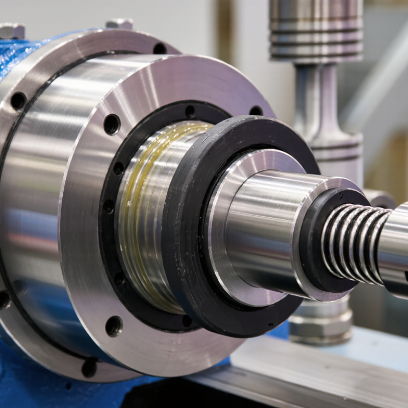
Dynamic seals operate where two surfaces move against each other. A rotary shaft seal uses a flexible lip to maintain contact around the shaft. Spring force supports the lip when pressure changes. A thin lubricant film reduces friction, heat, and surface damage. That film matters. Too little lubricant causes wear, while too much can increase leakage.
Piston seals and rod seals work differently inside hydraulic and pneumatic cylinders. They move with the piston or rod while blocking fluid and excluding dust. The U.S. Department of Energy’s Improving Compressed Air System Performance sourcebook reports that leaks can waste 20–30% of compressor output. This figure does not describe seal losses directly. It shows why small leakage paths deserve attention. Fluid Sealing Association guidance also stresses matching seal materials to pressure, temperature, speed, and media.
Selection should begin with operating conditions, not a catalog shape. Shaft runout, surface finish, pressure pulses, and installation angle can change performance. A seal that works in clean oil may fail quickly in abrasive slurry. The overlooked detail is installation. A small nick can become a visible leak within days. No seal lasts forever. Even a correctly selected seal needs inspection, lubrication control, and replacement planning. A dynamic seal is a working interface, not merely a spare part.
| Dynamic Seal Type | How It Works | Typical Motion | Typical Operating Range* | Key Advantages | Common Applications |
|---|---|---|---|---|---|
| O-Ring | An elastomeric ring is compressed in a groove. In dynamic service, it follows the moving surface while maintaining contact and preventing fluid or gas leakage. | Reciprocating or slow rotary motion | Approximately −40°C to 200°C; pressure commonly up to about 350 bar with suitable design and backup rings | Low cost, compact design, simple installation, and broad material availability | Hydraulic cylinders, pneumatic actuators, valves, pumps, and general machinery |
| Lip Seal | A flexible sealing lip presses against a shaft or rod. Fluid pressure can increase the contact force, while a garter spring may help maintain sealing force. | Rotary or reciprocating motion | Approximately −40°C to 180°C; shaft speeds often range from about 5 to 25 m/s, depending on material and lubrication | Effective contamination exclusion, economical replacement, and good performance in rotating equipment | Gearboxes, electric motors, pumps, wheel hubs, and hydraulic rods |
| Mechanical Face Seal | Two precisely lapped faces are pressed together by a spring or fluid pressure. A very thin lubricating film between the faces limits leakage and wear. | Rotary motion | Approximately −20°C to 250°C; pressure and speed depend strongly on face materials, fluid, and cooling | Very low leakage, high reliability, and suitability for demanding fluids and pressures | Centrifugal pumps, mixers, agitators, compressors, and process equipment |
| PTFE-Based Seal | A low-friction PTFE sealing element is energized by an O-ring, spring, or system pressure to maintain contact with the moving surface. | Rotary, reciprocating, or helical motion | Approximately −60°C to 260°C; high sliding speeds are possible with proper lubrication and heat control | Low friction, strong chemical resistance, and broad temperature capability | Chemical processing, hydraulic systems, valves, compressors, and high-speed machinery |
| V-Ring Seal | A flexible V-shaped seal rotates with the shaft. Its axial lip contacts a stationary surface and helps block water, dust, and other contaminants. | Rotary motion | Approximately −40°C to 200°C; speed capability depends on diameter, lip design, and installation | Excellent contamination protection, low friction, and easy installation | Bearings, agricultural machinery, conveyors, electric motors, and outdoor equipment |
| Wiper Seal | A wiping lip removes dirt, moisture, and particles from a reciprocating rod before they enter the primary sealing area. | Reciprocating motion | Approximately −40°C to 120°C; pressure is normally low and the seal is often used with a primary rod seal | Protects internal components, reduces abrasive wear, and improves seal system life | Hydraulic cylinders, telescopic equipment, mobile machinery, and construction equipment |
Why Choose a Dynamic Seal for Industrial Equipment?
Dynamic seals differ from static seals because they work while surfaces move. A rotating shaft, piston, or sliding rod passes through the sealing area. This movement creates friction, heat, and gradual wear. Static seals do not face this rubbing action. They remain still between fixed surfaces, such as a pipe flange or housing cover.
A dynamic seal must control leakage without restricting movement. Its design depends on shaft speed, pressure, temperature, lubrication, and surface finish. Even a small misalignment can create uneven contact. That can produce a narrow wear track, visible as a polished ring on the shaft. During equipment inspections, technicians often find that poor installation causes more damage than normal operation.
The distinction sounds neat, but real machines are less tidy. A seal may remain static during shutdown and become dynamic during operation. I have seen maintenance teams choose a seal by size alone, then overlook heat or chemical exposure. That decision can shorten service life. Material compatibility matters. So does correct compression. A dynamic seal with too much contact may overheat, while too little contact may leak. These failures are not always dramatic. Sometimes, a thin film of oil appears first. Careful inspection, accurate measurements, and operating records help reveal the actual cause.
Dynamic seals are designed to maintain a fluid barrier while a shaft, rod, or piston moves. The chart compares representative operating-speed ranges for common sealing arrangements; actual limits depend on pressure, temperature, lubrication, surface finish, material, and equipment design.
Static seals are intended for interfaces with no relative movement. Dynamic seals use suitable sealing lips, geometries, and materials to accommodate motion while limiting leakage and protecting surrounding components.
Dynamic seals protect industrial equipment where parts move against each other. They maintain a barrier around rotating shafts, pistons, and rods. This helps prevent oil, water, or process fluid from escaping. It also blocks dust and moisture from entering sensitive assemblies.
The key benefit is controlled leakage. A properly selected seal keeps an oil film between its sealing lip and the shaft. This reduces friction, heat, and surface wear during continuous operation. In pumps and hydraulic cylinders, that can support steadier pressure and fewer unplanned stoppages. Dynamic seals also handle movement better than static seals. Their flexible materials can follow small changes in alignment and vibration.
Maintenance teams often value their practical service benefits. A seal that performs consistently can reduce fluid loss, cleanup work, and replacement frequency. Still, a dynamic seal is not a universal fix. I have seen premature failures caused by rough shafts, excessive speed, or incompatible fluids. Small scratches can become leakage paths within hours. Temperature matters too, especially near heated bearings or compressed-air systems. Engineers should check pressure, shaft finish, motion type, lubrication, and chemical exposure before choosing a design. Installation deserves equal attention. A twisted lip or damaged edge may fail before the machine reaches normal operating speed. That detail is easy to overlook.
Why Choose a Dynamic Seal for Industrial Equipment?
How to Select the Right Dynamic Seal for an Application
Selecting a dynamic seal begins with understanding the equipment’s movement. Rotary shafts, reciprocating rods, and oscillating joints create different wear patterns. Record shaft speed, stroke length, pressure, and operating temperature before choosing a design. Temperature matters. A seal that performs well at room temperature may harden or soften inside a hot pump.
The working medium also controls material selection. Oil, water, steam, chemicals, and abrasive slurries can attack elastomers differently. Check compatibility data from reliable technical sources, then compare it with actual operating conditions. Pressure spikes deserve attention, especially during startup or shutdown. A seal may survive normal pressure but fail when the system suddenly surges. Surface finish, hardness, runout, and shaft condition should also be measured. Small scratches can become leakage paths.
Installation details are often underestimated. Confirm the groove dimensions, seal orientation, clearance, and available tools. Avoid stretching the seal over sharp edges. I have seen careful designs fail because technicians installed a suitable seal into a damaged housing. That mistake is easy to miss. Consider friction, expected service life, maintenance access, and acceptable leakage limits. If conditions are uncertain, test the seal under realistic speed, pressure, temperature, and media exposure before full production. Document the results, including failures, because an imperfect trial can reveal assumptions that calculations overlook.
Dynamic seals earn their place where rotating shafts meet pressure, heat, and abrasive fluids. In field inspections, the seal face often reveals the problem first: a polished track, dark heat marks, or fine slurry trapped near the gland. Common face materials include carbon, silicon carbide, and tungsten carbide. PTFE, EPDM, NBR, and FKM elastomers support different temperature and chemical conditions. Material selection must follow the actual fluid, not a catalogue habit.
Design matters as much as material. Pusher seals tolerate some movement, while bellows designs reduce sliding friction and resist certain deposits. Balanced designs can lower face loading in high-pressure service. The U.S. Department of Energy reports that pumping systems may consume 25–50% of industrial facility electricity. Small leakage and friction losses can therefore become expensive. ISO 21049 also emphasizes suitable seal arrangements, auxiliary systems, and operating limits. Still, a technically correct design can fail after poor installation.
Maintenance should record leakage, vibration, shaft runout, temperature, and flush pressure. Inspectors should check face condition during planned outages, not only after a visible leak. Clean flush fluid helps prevent solids from scoring the faces. A neglected filter can undo a carefully selected material pair. That shortcut often looks harmless. It is not. The U.S. DOE Pumping System Assessment Tool guidance supports measuring operating conditions before efficiency decisions, yet many maintenance teams still rely on sound alone. A practical log, clear limits, and periodic review usually outperform memory. Mistakes happen, especially when fluid chemistry changes without updating the seal specification.
| Cookie | Duration | Description |
|---|---|---|
| cookielawinfo-checkbox-analytics | 11 months | This cookie is set by GDPR Cookie Consent plugin. The cookie is used to store the user consent for the cookies in the category "Analytics". |
| cookielawinfo-checkbox-functional | 11 months | The cookie is set by GDPR cookie consent to record the user consent for the cookies in the category "Functional". |
| cookielawinfo-checkbox-necessary | 11 months | This cookie is set by GDPR Cookie Consent plugin. The cookies is used to store the user consent for the cookies in the category "Necessary". |
| cookielawinfo-checkbox-others | 11 months | This cookie is set by GDPR Cookie Consent plugin. The cookie is used to store the user consent for the cookies in the category "Other. |
| cookielawinfo-checkbox-performance | 11 months | This cookie is set by GDPR Cookie Consent plugin. The cookie is used to store the user consent for the cookies in the category "Performance". |
| viewed_cookie_policy | 11 months | The cookie is set by the GDPR Cookie Consent plugin and is used to store whether or not user has consented to the use of cookies. It does not store any personal data. |